How to Schematic diagram of RO Plant with RO Components
Por um escritor misterioso
Descrição
How to Schematic diagram of RO Plant with RO Components? The separation takes place in a dense polymer barrier layer in reverse osmosis membranes. Because Reverse

Processes, Free Full-Text

Industrial Water Softener Parts, Benefits, Applications & Diagram

Flow diagram of the RO pilot plant No. 1.

R O Complete Diagram

a) Indigenously fabricated RO plant (b) Flow Sheet diagram of
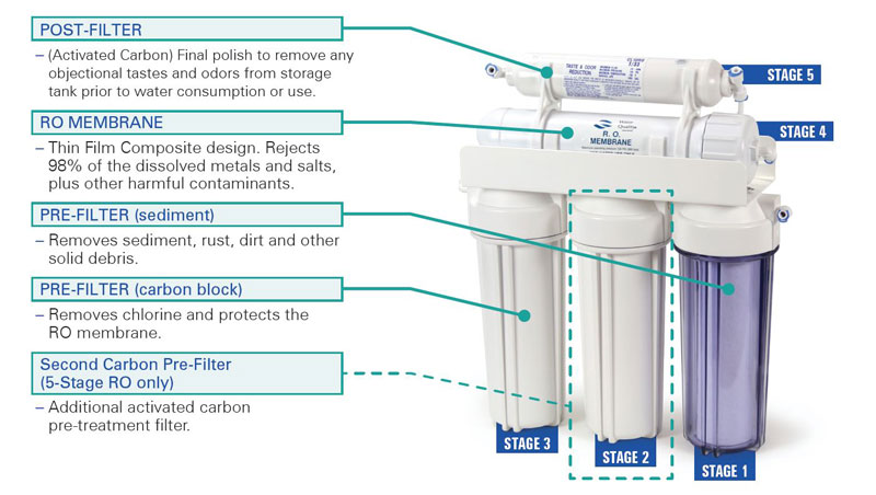
Nelsen NR05-50 5-Stage Reverse Osmosis System 50 GPD
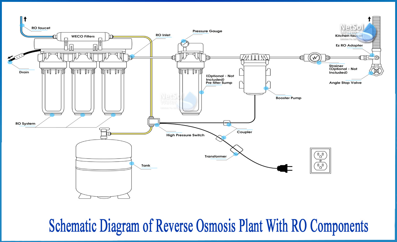
How to Schematic diagram of RO Plant with RO Components

Dialysis Water Treatment
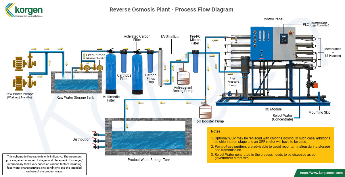
Reverse Osmosis (RO) Systems, Desalination Plants
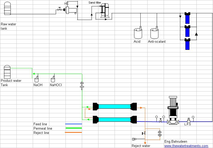
Flow Diagram Of Reverse Osmosis Plant, Water Treatment

RO/DI Filters & Aquariums – Whitlyn Aquatics

500032 - 5SV Guide

Flexible reverse osmosis (FLERO) desalination - ScienceDirect

